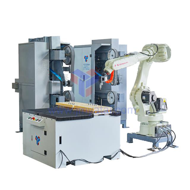
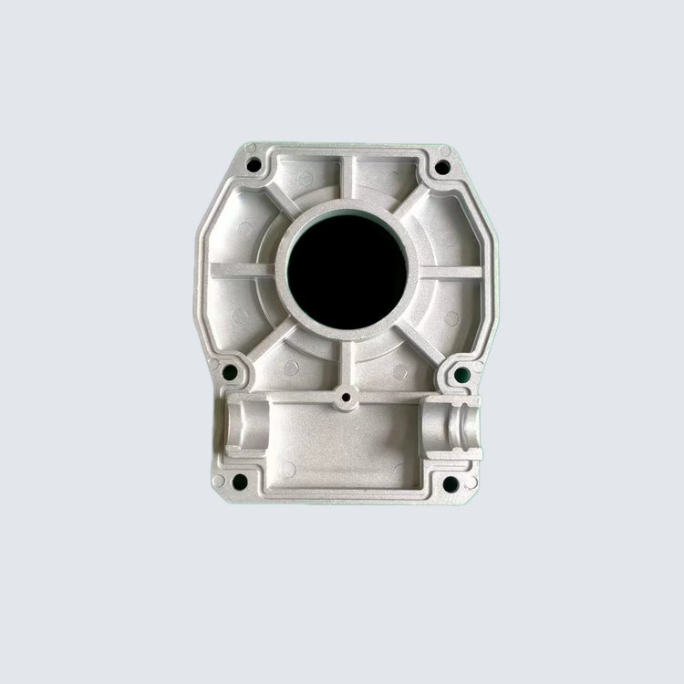
The automotive industry's transition toward tighter manufacturing tolerances, complex lightweight alloys, and high-volume production exposes the critical limitations of manual material removal. Balancing the demand for consistent surface finishes on complex geometries against strict cycle time constraints, labor shortages, and high scrap costs is a daily operational hurdle. Engine blocks, transmission housings, body panels, and structural welds all require precise surface preparation to meet modern quality standards before downstream processing.
Moving from manual or rigid CNC processes to a robotic Grinding Machine requires a rigorous evaluation of force control, system configuration, and integration capabilities. This guide breaks down the technical criteria for selecting a system that delivers measurable results without introducing unmanageable production risks. We will look at specific hardware configurations, compliance mechanisms, and integration strategies that directly impact cycle times and surface finish quality on the factory floor.
Force Control is the Differentiator: The choice between active compliance and passive compliant force control devices dictates whether a robotic grinding cell achieves consistent surface finishes or results in high scrap rates.
Configuration Dictates Capacity: Selecting between part-to-process and process-to-part setups depends entirely on component payload, geometry, and specific automotive cycle time requirements.
Integration Over Hardware: A high-quality grinding machine spindle is only as effective as its integration with end-of-arm tooling (EOAT), compliant angle grinders, 3D vision systems, and environmental safety controls.
Turnkey vs. Component-Based Sourcing: Decisions between single-source turnkey grinding cells and custom-integrated "best-of-breed" components radically impact deployment timelines and internal maintenance requirements.
Table of Contents
Toggle
Success Criteria: Defining the Automotive Grinding Problem
Material Removal Tolerances in Automotive Manufacturing
Powertrain components like cylinder heads and crankshafts demand distinct surface finishes compared to structural body parts. Weld seam leveling, deburring, and gate removal on castings require precise material removal to maintain structural integrity. You must analyze the specific tolerances required for each component type to configure the cell correctly. For instance, a cast iron engine block might require aggressive gate removal with a heavy-duty abrasive wheel, while an aluminum steering knuckle needs careful flash removal to avoid gouging the softer base metal.
Surface preparation is essential for downstream automotive processes. E-coating, painting, and high-precision sealing rely on flawless substrates. Any surface defect can compromise paint adhesion or cause fluid leaks in powertrain assemblies. When a robotic Grinding Machine leaves chatter marks or uneven radii, the subsequent sealing gaskets will fail under pressure testing. This means the material removal process is not just about aesthetics; it is a functional requirement for vehicle reliability.
Over-grinding, under-grinding, and part scrap rates heavily impact financial outcomes in high-volume, automated automotive production environments. A single poorly processed batch can halt an entire assembly line, making consistent material removal a critical production metric. If a robot removes too much material from a transmission housing mating surface, the entire casting is scrapped. If it removes too little, the part fails automated inspection and requires manual rework, defeating the purpose of automation.
Component Type
Typical Material
Primary Grinding Task
Tolerance Sensitivity
Engine Blocks
Cast Iron / Aluminum
Gate removal, heavy flash grinding
High (Mating surfaces require strict flatness)
Structural Body Panels
High-Strength Steel
Weld seam leveling
Medium (Focus on paint adhesion and aesthetics)
Transmission Gears
Hardened Steel
Precision deburring, edge radiusing
Very High (Micro-burrs cause catastrophic failure)
Steering Knuckles
Forged Aluminum
Parting line removal
High (Suspension geometry depends on exact dimensions)
The Limitations of Traditional CNC and Manual Grinding
Manual grinding operations present severe ergonomic hazards. Operators face vibration-induced white finger (VWF), dust inhalation risks, and throughput inconsistencies. Human operators cannot maintain the exact same applied force and feed rate over an entire shift, leading to inevitable quality variations. By the end of an eight-hour shift, operator fatigue naturally results in slower cycle times and a higher likelihood of under-grinding complex contours.
Traditional, rigid CNC setups lack flexibility. They struggle with part-to-part casting variations, flashing, parting line shifts, and complex multi-axis geometries. When a casting deviates slightly from the CAD model, a rigid CNC toolpath will either gouge the part or miss the material entirely. CNC machines expect the part to be exactly where the program says it is. In foundry environments, castings shrink, warp, and shift. A rigid spindle cannot adapt to these physical realities, leading to high scrap rates and broken tooling.
Core Configurations of a Robotic Grinding Machine Cell
Process-to-Part (Tool on Robot)
In this configuration, the robot arm manipulates the spindle, compliant angle grinder, or belt tool across a stationary automotive component. The part remains fixed in a heavy-duty fixture while the robot performs the material removal. This setup mimics how a human operator would use a hand grinder on a large workpiece.
This setup is highly suited for heavy, large-scale automotive components. Chassis frames, large engine castings, and structural body panels fit this model perfectly when moving the part is unfeasible. It allows the robot to reach inside cavities, navigate complex external geometries, and process multiple weld seams on a single large assembly without needing massive external positioners.
It requires robust robot payload capacity. The arm must handle the weight of the spindle, drive motors, and force compliance devices without sacrificing path accuracy or introducing tool chatter. You must select a robot with high rigidity to withstand the reactive forces generated during aggressive material removal. A standard handling robot will deflect under heavy grinding loads, causing the abrasive to bounce off the part. You need a foundry-grade robot specifically designed for high-payload machining tasks.
Part-to-Process (Part on Robot)
Here, the robot grips the automotive component and manipulates it against a stationary pedestal Grinding Machine, automated belt grinder, or buffing unit. The tool remains fixed to the floor or a rigid stand while the part moves across the abrasive media.
This configuration is ideal for smaller, high-precision components. Transmission gears, brackets, steering knuckles, and manifold castings allow the robot to easily manipulate the part's orientation. It often yields faster cycle times for small parts because the robot can move the lightweight component faster than it could move a heavy spindle. It also simplifies dust collection, as the extraction hood can be permanently mounted directly behind the stationary contact wheel.
It requires highly precise end-of-arm grippers and a stationary machine capable of continuous heavy-duty operation. Automated regripping stations help process multiple faces of the component without manual intervention. If the robot needs to grind all six sides of a casting, it will place the part on a temporary stand, adjust its grip, and pick it back up to finish the remaining surfaces.
Technical Evaluation Dimensions: Features to Outcomes
Force Control and Compliance Mechanisms
Evaluate passive compliant force control devices carefully. Pneumatic or spring-loaded mechanical compliance maintains constant contact force using predefined air pressure or mechanical tension. These devices are mechanically simple and highly reliable for basic deburring tasks. They allow the spindle to float slightly, absorbing minor casting variations without requiring complex software programming. However, they only apply force in one specific direction, limiting their use on highly complex 3D contours.
Assess active compliance systems for complex geometries. Closed-loop force-torque sensors dynamically adjust real-time force feedback at millisecond intervals to compensate for part deviations. This allows the robot to "feel" the surface and adjust its path instantly. If the abrasive encounters a thick gate, the sensor detects the resistance and signals the robot to slow down and apply more pressure until the material is removed.
Consistent contact force directly prevents tool chatter. It avoids heat-induced microstructural damage and localized under- or over-grinding on complex automotive contours. Proper force control ensures the abrasive media cuts efficiently without glazing or prematurely wearing down. When you push an abrasive belt too hard, the grains fracture prematurely. When you don't push hard enough, the belt rubs and generates excessive heat, which can warp thin-walled aluminum castings.
Grinding Spindles, Tooling, and Buffing Integration
Evaluate spindle specifications based on your production demands. Look at continuous duty cycles, horsepower ratings, torque curves under load, and bearing protections for 3-shift automotive environments. A spindle that bogs down under load will ruin the surface finish and destroy abrasive belts. You need a spindle that maintains its RPM even when hogging out heavy cast iron gates. Water-cooled spindles often provide better longevity in these high-stress applications compared to air-cooled variants.
Integrate specialty tooling like compliant angle grinders, deburring tools, and axial compliance units. The ability to swap tools automatically increases the cell's versatility. A tool changer allows the robot to drop a heavy grinding wheel and pick up a fine wire brush to finish a machined face within the same cycle.
Evaluate the machine's capacity to transition from aggressive grinding and gate removal to fine buffing, polishing, and edge radiusing within a single cell cycle. This multi-process capability reduces part handling and overall cycle time. Ensure compatibility with diverse abrasive media. Grinding wheels, abrasive belts, rotary burrs, and non-woven wheels must suit automotive metals like cast iron, aluminum alloys, and high-strength steel. The right abrasive paired with the right spindle speed dictates the success of the operation.
Vision Systems and Adaptive Software
Assess the role of 2D and 3D vision systems. They identify casting variations, verify weld seam heights, and dynamically shift toolpaths before the abrasive makes contact. Vision systems eliminate the need for perfect part fixturing. If a casting is loaded into the cell slightly skewed, the 3D camera scans the part, calculates the offset, and shifts the entire robot coordinate system to match the actual part location.
Software utilizes real-time force and vision feedback. It adjusts feed rates and spindle speeds based on the actual material volume to be removed. If a weld seam is thicker than expected, the software slows the robot down to maintain a consistent finish. This adaptive behavior is what separates a modern robotic cell from a blind CNC machine.
Evaluate the necessity of offline programming (OLP) software. OLP generates complex multi-axis toolpaths, simulates cycle times, and avoids collision risks without halting the active production line. You can program the next vehicle model while the current one is still running. OLP allows engineers to import the CAD model of the part, generate the toolpath, and verify that the robot arm won't crash into the fixture during complex maneuvers.
Value Influencing Factors and Conceptual Trade-offs
Single-Source Turnkey Cells vs. Custom Integration
Purchasing a complete system from a single source offers faster deployment. It includes the robot, enclosure, spindle, dust collection, and software, simplifying warranty support. You have one point of contact if something goes wrong. Turnkey providers have already solved the integration headaches between the robot controller and the force sensor. They deliver a working cell that you bolt to the floor and supply with power and air.
Building a custom cell uses best-of-breed components. Pairing a specific robot brand with dedicated compliance tooling and proprietary software meets rigid factory specifications. This approach requires more engineering effort upfront but often results in a highly optimized process. If your plant standardizes on a specific PLC and robot brand, custom integration ensures the new cell matches your existing maintenance protocols and spare parts inventory.
Flexibility vs. Cycle Time
Highly adaptive robotic cells offer rapid changeover for new vehicle models and varying geometries. However, they may have slightly longer cycle times compared to dedicated, rigid transfer lines. You must weigh the value of flexibility against raw throughput. A hard-tooled broaching machine will always remove material faster than a robot, but it can only process one specific part. When the vehicle model changes, the hard tooling goes to the scrapyard.
Calculate the return on investment based on vehicle production volume, platform lifecycles, and model variation frequency. If you run high-mix, low-volume production, flexibility is paramount. For low-mix, high-volume, cycle time dictates the design. A robotic cell allows you to run left-hand and right-hand steering knuckles on the same shift simply by calling up a different program.
Upfront CapEx vs. Abrasive Consumable Optimization
A higher upfront investment in active force-controlled tooling and precision spindles dramatically reduces long-term operational expenditures. Cheap spindles vibrate, which destroys abrasives quickly. Vibration causes the abrasive grains to shatter rather than cut, forcing you to replace belts and wheels twice as often.
Controlled, precise force application optimizes abrasive media wear. It extends belt and wheel lifespans and reduces downtime required for tool changes. Spending more on the initial hardware directly lowers your daily consumable costs. When the robot applies the exact right amount of pressure, the abrasive performs exactly as the manufacturer intended, yielding predictable wear rates and consistent surface finishes.
Implementation Risks and Mitigation Strategies
Managing Dust, Swarf, and Environmental Hazards
Processing aluminum and magnesium automotive parts presents severe explosion and fire risks. Combustible dust requires strict management to protect the facility and personnel. When aluminum dust mixes with oxygen and an ignition source like a stray spark from a grinding wheel, the resulting deflagration can destroy a facility.
Implement wet-grinding configurations, specialized extraction systems, and explosion vents. Ensure compliance with local environmental and safety standards like ATEX and NFPA. Dust collection systems must be interlocked with the robot controller to prevent operation if extraction fails. If the airflow drops below a safe threshold, the PLC must immediately halt the spindle and stop the robot to prevent dust accumulation inside the enclosure.
System Integration, Calibration, and Tool Wear Compensation
Address the mechanical reality of Tool Center Point (TCP) drift. Continuous wheel wear, belt stretching, and thermal expansion of the robotic spindle cause this drift. If uncorrected, the robot will miss the part entirely. A grinding wheel that starts at 300mm in diameter will slowly shrink to 200mm. The robot must know exactly how large the wheel is at all times to maintain the correct surface speed and contact point.
Recommend mitigation strategies like automatic mechanical probes, laser-based tool setters, and software algorithms. These automatically adjust robot paths to compensate for progressive wheel degradation. The robot touches off on a sensor periodically to update its TCP. This routine takes only a few seconds but guarantees the toolpath remains accurate throughout the entire lifespan of the abrasive media.
Evaluate automated tool and media changeover systems. They swap worn wheels, belts, or burrs without requiring human intervention inside the safety enclosure. This keeps the spindle running and operators safe. When the laser setter detects the wheel has reached its minimum usable diameter, the robot automatically drops the worn tool into a bin and picks up a fresh one from the magazine.
Conclusion
A robotic Grinding Machine is a highly engineered system requiring precise integration of force control, robust spindles, and adaptive software to meet rigid automotive standards. To ensure a successful deployment, follow these actionable steps:
As an established global leader in turnkey industrial automation and high-precision material removal technology, Yatai engineers advanced robotic grinding machine cells tailored for the harsh operating environments of modern automotive foundries and assembly plants. Our automated systems integrate ultra-responsive force compliance devices, intelligent tool wear compensation software, and explosion-proof dust extraction to systematically eliminate manual finishing inconsistencies, allowing manufacturers to maximize component first-pass yields while maintaining world-class workplace safety standards.
Prioritize system integrators and OEMs who offer feasibility studies, cycle time simulations, and proof-of-concept testing using your specific automotive castings and production materials.
Conduct an internal audit of manual scrap rates and cycle times to establish a firm baseline for operational improvement.
Evaluate the physical footprints required for process-to-part versus part-to-process cells on your factory floor.
Request high-fidelity simulation models from prospective vendors to verify reach, cycle capability, and collision avoidance.
FAQ
Q: What is the difference between a robotic grinding machine and a traditional CNC grinder?
A: A traditional CNC grinder is highly rigid and relies on exact part positioning, making it inflexible to casting variations. A robotic system utilizes articulated arms and force compliance to adapt to part-to-part inconsistencies, offering greater flexibility for complex geometries.
Q: How does a passive compliant force control device compare to active force control?
A: Passive compliance uses mechanical springs or pneumatic pressure to maintain a constant force, which is simple and cost-effective. Active force control uses closed-loop sensors to dynamically adjust force in real-time, providing superior accuracy for complex contours.
Q: Can a single robotic grinding cell handle both aggressive grinding and fine buffing/polishing?
A: Yes. By utilizing automated tool changers and variable speed spindles, a single cell can switch from aggressive material removal tools to fine polishing media within the same cycle.
Q: How does the system compensate for progressive wear on the grinding wheel or abrasive belt?
A: The system uses laser tool setters, mechanical touch-off probes, and software algorithms to measure the tool's diameter periodically. It then automatically updates the Tool Center Point (TCP) to maintain accurate contact with the part.
Q: What are the key safety and dust extraction requirements for a robotic grinding cell processing aluminum?
A: Processing aluminum creates combustible dust. The cell requires specialized wet-grinding setups or ATEX/NFPA-compliant dry extraction systems with explosion vents to mitigate severe fire and explosion risks.
Q: Is it better to source a turnkey grinding cell from a single vendor or integrate custom components?
A: Turnkey cells offer faster deployment and simplified warranty support. Custom integration allows you to select best-of-breed components tailored to highly specific factory requirements, though it requires more engineering oversight.
Q: How does offline programming software prevent collision risks and minimize programming downtime?
A: Offline programming allows engineers to build and simulate complex multi-axis toolpaths in a virtual environment. This identifies collisions before they happen and lets you program new parts without stopping the physical production line.