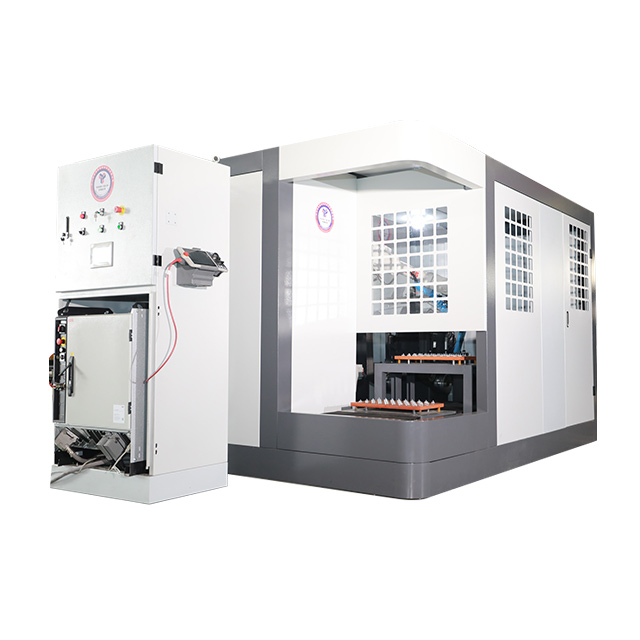
Surface finishing remains the most labor-intensive and high-variance bottleneck in sanitary ware production. Manufacturers constantly battle the physical limitations of manual labor when processing complex faucet geometries. Compound curves, tight radii, and dense substrates like brass or zinc alloy demand precise, consistent abrasive contact. Relying on manual operators introduces inconsistent quality, high scrap rates, and severe occupational health hazards from metal dust exposure. Automated finishing systems offer a definitive way out of this bottleneck. Transitioning to a Robot Polishing Machine represents a critical facility upgrade. It guarantees production repeatability, stabilizes unit output, and enables scalable throughput. Modern manufacturing demands deterministic results. Robotic systems deliver exactly that, transforming unpredictable manual grinding into a highly controlled, data-driven process.
Table of Contents
Toggle
Key Takeaways
Force Control is Non-Negotiable: Active force-controlled robotic systems are mandatory for faucet manufacturing to maintain consistent abrasive contact across complex, non-linear surfaces.
ROI Extends Beyond Labor: While reducing headcount is a primary driver, the true ROI of a robot polishing machine includes drastically reduced scrap rates, lower consumable waste, and predictable production scheduling.
Programming Complexity is the Main Hurdle: Evaluating offline programming (OLP) capabilities and digital twin simulation is just as critical as evaluating the physical hardware.
Integration Requires Synergy: Optimal setups often utilize multiple robotic arms working in synergy within an enclosed, environmentally controlled workstation to handle grinding, buffing, and final polishing sequentially.
The Business Case for Automating Faucet Finishing
Manual vs. CNC vs. Robotic Polishing: Analyzing the Variance
Manual polishing inherently suffers from statistical variance. Operator fatigue, inconsistent applied pressure, and shift-to-shift quality drift make it impossible to guarantee identical surface finishes across a production run. A manual operator might apply 10 pounds of force at the start of a shift and only 6 pounds by the end. This discrepancy alters the material removal rate. Automated systems eliminate this variance entirely. They provide deterministic output where every single workpiece receives the exact same abrasive treatment, regardless of the time of day.
Traditional CNC automatic metal polishing machines handle simple, symmetrical, or cylindrical geometries well. However, they fail when confronted with the organic, non-symmetrical, and compound curves of modern faucet designs. A multi-axis Robot Polishing Machine provides the necessary articulation to navigate these complex shapes. The robot arm mimics the dexterity of a human wrist but adds relentless precision and repeatability. It can twist and angle the workpiece to ensure the abrasive wheel contacts the tightest inside corners of a faucet spout.
Surface finish variance directly impacts subsequent plating or PVD coating processes. Microscopic imperfections, uneven grain structures, or missed contours lead to immediate plating rejection. When brass castings have uneven surface tension due to poor polishing, the electroplating process magnifies these defects. Automated polishing ensures uniform surface roughness, drastically reducing the rejection rate at the plating line. This predictable surface preparation is essential for maintaining high yield rates in the final finishing stages.
Polishing Method
Geometry Capability
Quality Variance
Throughput Scalability
Plating Rejection Risk
Manual Polishing
High (Human dexterity)
High (Fatigue, shift drift)
Low (Requires linear hiring)
High (Inconsistent Ra values)
CNC Automatic
Low (Symmetrical only)
Low (Consistent)
Medium (Fast but limited scope)
Medium (Missed complex curves)
Robotic Polishing
High (6-axis articulation)
Zero (Deterministic)
High (Lights-out capable)
Low (Uniform surface preparation)
Unit Cost Reduction and Throughput Scaling
Evaluating unit economics reveals the distinct advantage of automation. Manufacturers must weigh amortized equipment costs, electricity, and optimized consumables against hourly wages, benefits, and scrap costs. Robots apply exact pressure, which prevents premature wear on abrasive belts and polishing compounds. When a human operator pushes too hard, the abrasive grains fracture prematurely. A robot maintains the optimal cutting pressure, extending consumable life significantly. This reduction in abrasive waste directly lowers the per-unit processing cost.
Automated systems also enable minimally supervised or completely lights-out shifts. Facilities can run production continuously. This effectively doubles or triples daily throughput without requiring proportional labor scaling. Predictable production scheduling becomes a reality when machine uptime replaces human availability. You can load a pallet of raw brass castings into an automated infeed system at 5:00 PM and return the next morning to a pallet of perfectly polished parts ready for the plating line.
Furthermore, the reduction in scrap parts cannot be overstated. In manual operations, a momentary lapse in concentration can gouge a brass casting beyond repair. The robot follows its programmed path with sub-millimeter accuracy. It does not get distracted, and it does not make arbitrary movements. This consistency ensures that nearly 100% of the raw castings entering the polishing cell exit as viable, high-quality components.
Core Technologies in a Modern Robot Polishing Machine
Active Force-Controlled Multi-Functional Workstations
Material removal requires precise pressure. Passive force control relies on mechanical compliance, like springs or pneumatic cylinders, which can be sluggish and imprecise. Active force control uses closed-loop sensors, typically load cells mounted on the robot wrist or the spindle, to detect resistance instantly. The system dynamically adjusts the robot's applied pressure in milliseconds. If the abrasive wheel encounters a slightly thicker parting line on a casting, the force sensor detects the increased resistance and signals the robot controller to adjust the feed rate or pressure accordingly.
Active force control is critical for processing faucets. Castings often have slight dimensional variations from the foundry. Abrasive tools wear down during operation, changing their effective diameter. The robot must compensate for these variables without altering the programmed path. Active sensors ensure uniform material removal across every millimeter of the brass or zinc substrate. Without active force control, the robot would either miss the surface entirely as the wheel wears down or gouge the part if the casting is slightly oversized.
Implementing active force control requires sophisticated software algorithms. The controller must process the sensor data and adjust the robot's trajectory in real-time. This requires high-speed communication protocols between the force sensor, the robot controller, and the spindle drive. When properly calibrated, an active force-controlled Robot Polishing Machine can maintain a constant contact force of exactly 15 Newtons, for example, across a complex 3D contour, ensuring a perfectly uniform scratch pattern.
Multi-Axis Robotic Arms and Kinematic Flexibility
Modern faucet designs feature intricate contours, sweeping spouts, and sharp handle angles. Standard machinery cannot reach these tight radii. You need 6-axis or 7-axis robotic arms to navigate these complex geometries effectively. The extra degrees of freedom allow the abrasive tool to maintain continuous, perpendicular contact with the surface. A 6-axis robot can roll its wrist to follow the sweeping curve of a swan-neck spout while maintaining the exact optimal cutting angle for the abrasive belt.
Workcell configurations generally fall into two categories. In a part-to-tool setup, the robot grips the faucet and moves it against stationary abrasive wheels. This is highly effective for heavy brass castings. The robot acts as the material handler and the manipulator. In a tool-to-part setup, the robot holds the polishing tool and moves it over a fixtured component. This often suits lighter parts or massive assemblies that are difficult to manipulate. For sanitary ware, part-to-tool is the dominant configuration because it allows a single robot to utilize multiple different abrasive stations within its reach envelope.
The kinematic flexibility of a 6-axis arm also simplifies tool center point (TCP) calibration. The TCP is the exact point in space where the polishing action occurs. As abrasive wheels wear down, the TCP shifts. Advanced robotic controllers automatically recalculate the TCP based on sensor feedback or periodic laser measurements. This ensures the robot's programmed path remains accurate even as the physical dimensions of the abrasive media change throughout the production shift.
Multi-Robot Synergy and Collaborative Workcells
Advanced workstations deploy multiple robotic arms working in synergy. This approach covers the polishing needs of a full faucet series efficiently. Instead of one robot performing all tasks sequentially, the workload is distributed. A typical high-volume cell might feature three robots arranged around a central rotary table or conveyor system. This division of labor allows each robot to specialize in a specific stage of the finishing process, optimizing cycle times.
Process handoffs create massive efficiency gains. Robot A might perform heavy grinding to remove casting lines using a coarse P80 belt. It then hands the part to Robot B, which simultaneously handles fine polishing using a P320 belt and a sisal wheel. Finally, Robot C performs the final color buffing using a cotton wheel and polishing compound. This concurrent processing slashes cycle times and maximizes equipment utilization. While Robot C is finishing the first part, Robot A is already grinding the third part.
Synchronizing multiple robots requires robust industrial communication networks. Protocols like EtherCAT or PROFINET ensure that the robots, safety scanners, and spindle drives communicate with microsecond latency. This prevents collisions when robots share the same workspace and ensures smooth handoffs. The central programmable logic controller (PLC) orchestrates the entire cell, tracking each workpiece as it moves through the various abrasive stages.
Abrasive Media and Contact Wheel Configurations
A single Robot Polishing Machine integrates with various abrasive stations. The workcell typically includes abrasive belts, sisal wheels, and cotton buffs. Each station serves a specific stage of the finishing process. The contact wheels behind the abrasive belts come in various durometers (hardness levels). A hard, serrated rubber wheel provides aggressive cutting action for removing heavy flash, while a soft, smooth urethane wheel allows the belt to conform to the curved surfaces of the faucet body.
Automated media sequencing allows a raw casting to transition through multiple stages seamlessly. The system moves the part from coarse grinding to fine brushing, and finally to mirror polishing within one continuous cycle. Automated compound application systems spray liquid or solid paste precisely, ensuring optimal cutting action at each step. These applicators are tied to the robot controller, applying compound only when the wheel is in contact with the part, which drastically reduces consumable waste.
Coarse Grinding (P60 - P120): Removes parting lines, gates, and heavy casting defects using ceramic or zirconia alumina belts.
Intermediate Refining (P180 - P320): Smooths out the deep scratches left by the coarse grinding stage using aluminum oxide belts.
Pre-Polishing (Sisal Wheel): Blends the directional scratch patterns and prepares the surface for final buffing using a treated sisal wheel and cutting compound.
Final Color Buffing (Cotton Wheel): Achieves the high-gloss, mirror finish required before chrome plating using a loose cotton buff and a fine coloring compound.
Key Evaluation Dimensions for Faucet Manufacturers
Repeatability and Surface Finish Quality Metrics
Success criteria vary wildly based on the desired surface finish. Achieving a uniform linear grain for brushed finishes requires strict directional control. The robot must drag the abrasive fleece in perfectly straight lines across the faucet body. Achieving a specific low Ra (Roughness Average) value for high-gloss mirror finishes requires progressive abrasive stepping prior to chrome plating. If you skip a grit size, the final buffing stage will not remove the deep scratches left by the earlier grinding stages.
Buyers must demand empirical data during vendor proof-of-concept trials. Do not accept visual inspections alone. Require surface roughness testing using profilometers. The robotic system must prove it can hit the target Ra value consistently across a batch of test castings. A typical requirement for high-quality sanitary ware is an Ra value of less than 0.05 micrometers before plating. The vendor should provide a detailed quality report showing the statistical distribution of Ra values across a sample size of at least 50 parts.
Furthermore, evaluate the system's ability to maintain edge definition. Manual polishers often round over crisp design lines on modern, geometric faucets. A properly programmed robot will apply exact pressure and utilize the correct contact wheel durometer to polish the flat surfaces without destroying the sharp, intended edges of the design. This capability is crucial for maintaining the aesthetic integrity of high-end sanitary ware.
Programming, Path Generation, and Changeovers
The software ecosystem dictates operational agility. Traditional teach-pendant programming is incredibly time-consuming and requires high operator skill. Manually jogging a robot over a complex faucet contour, recording hundreds of individual waypoints, can take days. If the casting geometry changes slightly, the entire program must be manually adjusted. This downtime is unacceptable in modern manufacturing environments.
Modern Offline Programming (OLP) software changes this dynamic. OLP utilizes CAD-to-path generation. Engineers import the 3D model of the faucet and generate the polishing path virtually. The software automatically calculates the optimal tool angles, feed rates, and transition movements. This allows for rapid changeovers between different faucet SKUs, which is essential in high-mix, low-volume production environments. You can program the next part while the robot is actively polishing the current batch.
Advanced OLP platforms also include digital twin simulation. This allows engineers to visualize the entire robotic cell in a virtual environment. They can check for reachability issues, simulate cycle times, and detect potential collisions between the robot arm and the abrasive stations before a single line of code is sent to the physical machine. This virtual commissioning drastically reduces deployment time and prevents costly crashes on the factory floor.
Dust Extraction and Environmental Compliance
Polishing brass and zinc generates hazardous metal dust. Facility integration must include robust dust management. Wet polishing systems suppress dust at the source using liquid coolants. The coolant floods the contact zone, capturing the metal particles and carrying them away to a filtration unit. This method is highly effective but requires managing wastewater and drying the parts after processing.
High-velocity dry dust extraction systems pull particulates away from the work zone immediately. These systems use powerful centrifugal fans and custom-designed capture hoods positioned directly behind the abrasive wheels. The dust is transported through ductwork to a central dust collector equipped with HEPA filters and explosion-suppression panels.
This is a strict compliance and safety evaluation. Mitigating combustible metal dust risks ensures NFPA and ATEX compliance. Zinc and aluminum dust, in particular, are highly explosive when suspended in the air. Proper extraction also reduces the HVAC load in the facility, keeping the factory floor clean and protecting worker respiratory health. A clean robotic cell also prevents abrasive dust from infiltrating the robot's mechanical joints and the spindle bearings, extending the lifespan of the equipment.
Implementation Risks and Mitigation Strategies
Facility Integration and Floor Space Requirements
Manufacturers frequently underestimate the footprint of a fully enclosed robotic cell. The physical robot is only one component. You must account for safety fencing, massive dust collectors, automated tool changers, and part infeed/outfeed conveyors. A cell that looks compact on a CAD drawing can quickly consume a massive amount of floor space once you factor in maintenance access zones and material handling aisles.
Mitigate this risk by conducting 3D facility scanning. Request a complete workflow simulation from the integrator prior to finalizing the purchase order. Ensure the proposed layout allows for safe forklift access to the dust collector hoppers and smooth material flow for the raw castings and finished parts. Map out the exact routing for electrical drops, compressed air lines, and dust extraction ductwork to avoid surprises during installation.
Consider the structural requirements of the floor. Industrial robots generate significant dynamic loads as they accelerate and decelerate heavy payloads. The concrete slab must be thick enough and properly reinforced to handle these forces without transmitting vibrations to adjacent precision machinery. The integrator should provide detailed foundation requirements based on the specific robot model and payload.
Operator Upskilling and Maintenance Protocols
Replacing manual polishers means you must hire or upskill technicians. The new workforce will manage robot programming, troubleshoot faults, and perform preventative maintenance. Ignoring this shift in labor requirements leads to extended downtime. A highly advanced robotic cell is useless if the on-site maintenance team does not know how to recover from a simple servo fault or recalibrate a force sensor.
Mandate comprehensive vendor training programs as part of the integration contract. Ensure you have accessible localized support. Establish clear preventative maintenance schedules for high-wear components like spindle bearings, contact wheels, and automated lubrication systems. The maintenance team must be trained on how to properly dress the abrasive wheels, replace the contact wheel bearings, and perform routine backups of the robot controller software.
Develop a robust spare parts inventory strategy. Identify the critical components that have long lead times, such as specialized force sensors, spindle motors, and custom contact wheels. Keep these items in stock to minimize downtime in the event of a hardware failure. The initial investment in spare parts will pay for itself the first time it prevents a multi-day production stoppage.
Conclusion
Transitioning to an automated surface finishing workflow shifts sanitary ware production from an unpredictable, labor-intensive craft to a reliable, data-driven manufacturing loop. Overcoming the inherent challenges of processing complex faucet profiles requires a strict commitment to adaptive force monitoring, modern digital twin simulation, and robust dust mitigation.
As a globally recognized pioneer in industrial surface finishing automation and high-efficiency manufacturing solutions, Yatai engineers heavy-duty robot polishing machine cells specifically optimized to meet the strict aesthetic and structural demands of the modern sanitary ware industry. Our turnkey workstations seamlessly combine active force-controlled compliance, automated multi-media sequencing, and integrated explosion-proof extraction systems, empowering high-volume faucet manufacturers to stabilize unit costs, eliminate electroplating rejections, and protect shop floor personnel.
To ensure a successful deployment, follow these actionable steps:
Initiate a pilot study or request a Proof of Concept (PoC) from shortlisted integrators using your most complex faucet SKU.
Demand empirical surface roughness data (Ra values) from the PoC trials rather than relying on visual inspections alone.
Evaluate the vendor's Offline Programming (OLP) software to ensure it supports rapid CAD-to-path generation for quick changeovers.
Conduct a 3D facility scan to verify that the proposed robotic cell, including dust extraction and safety fencing, fits within your floor plan.
Establish a comprehensive training and preventative maintenance program with the vendor before finalizing the equipment installation.
FAQ
Q: What is the typical payback period for a robot polishing machine in faucet manufacturing?
A: The standard payback period ranges from 1.5 to 3 years. This calculation factors in direct labor savings, drastically reduced scrap rates, and consumable optimization. Running the automated cell across two or three shifts accelerates this timeline significantly.
Q: How do robotic polishers handle complex faucet geometries compared to CNC automatic polishers?
A: Robotic arms feature 6-axis or 7-axis articulation combined with active force control. This allows them to follow asymmetrical, organic contours smoothly. Rigid, fixed-axis CNC polishing machines simply cannot navigate these complex, non-linear shapes.
Q: What is active force control in robotic polishing?
A: Active force control is a closed-loop system where sensors detect surface resistance. The system adjusts the robot's applied pressure in real-time. This ensures uniform material removal despite tool wear or slight dimensional variations in the casting.
Q: Can one robot polishing machine handle both grinding and brushing/drawing?
A: Yes. In part-to-tool configurations, the robot moves the faucet between different abrasive stations. In tool-to-part setups, automatic tool changers swap grinding wheels for brushing tools, transitioning seamlessly from rough grinding to linear grain drawing.
Q: How long does it take to program a new faucet design?
A: Manual teach-pendant programming can take several days for a complex faucet. Modern CAD-based offline programming (OLP) software reduces this to hours or even minutes by generating paths directly from the 3D model.
Q: What are the maintenance requirements for automated polishing cells?
A: Routine maintenance includes checking spindle bearings, refilling automated lubrication systems, and replacing dust extraction filters. Technicians must also periodically recalibrate force sensors and inspect abrasive contact wheels for uneven wear.