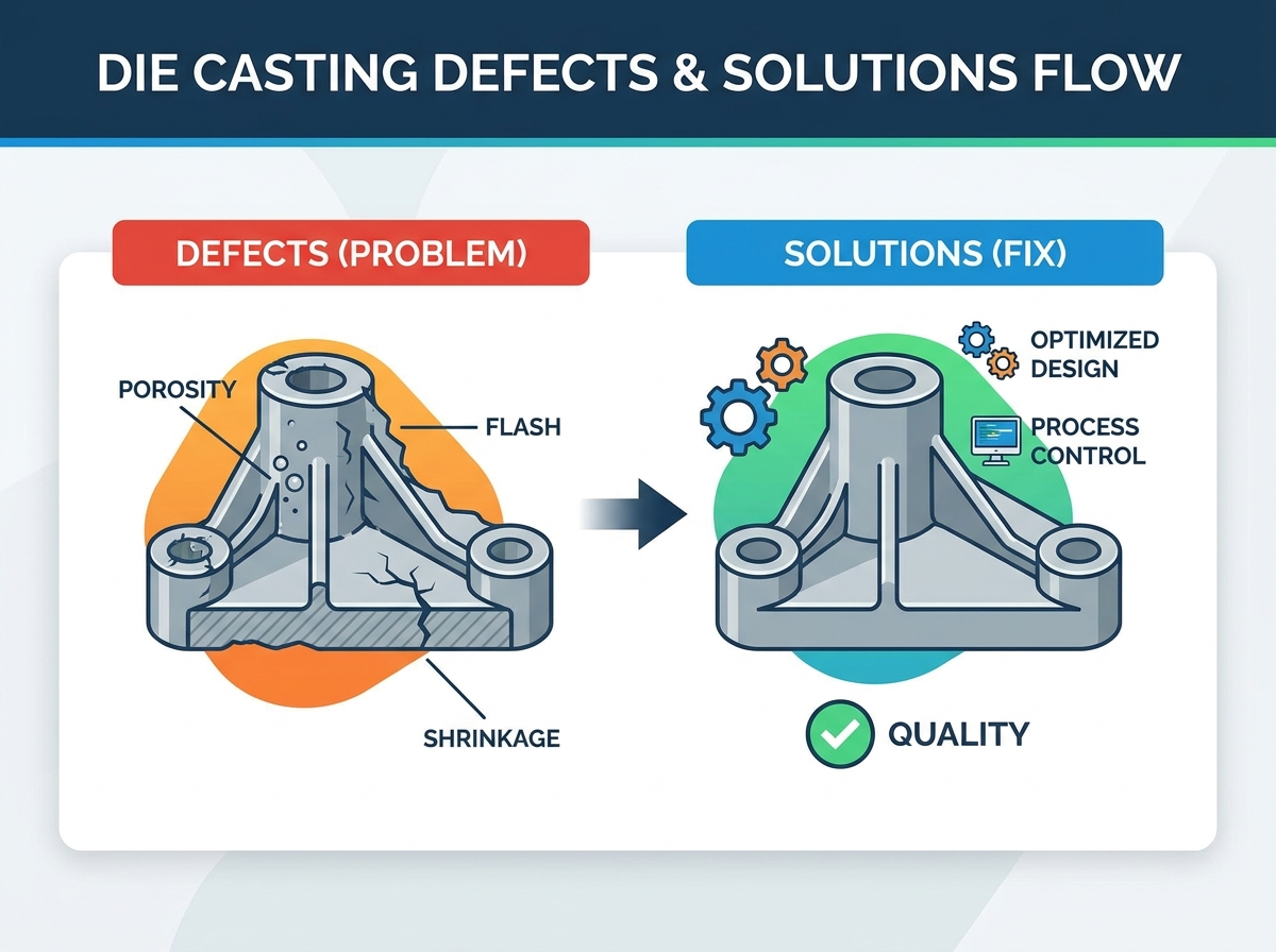
Die casting defects can increase scrap rates, rework costs, and product failure risks. Common problems include porosity, cold shuts, cracks, flash, and surface irregularities. These defects may affect dimensional accuracy, appearance, mechanical performance, or pressure tightness.
Effective defect prevention starts with identifying the root cause rather than relying only on final inspection. Engineers must evaluate casting design, alloy quality, mold conditions, machine settings, and downstream processing.
This guide explains common die casting defects, their possible causes, inspection methods, and prevention strategies. It also outlines how to evaluate a die casting supplier and determine when secondary finishing can improve part quality.
Table of Contents
Toggle
1. The Business Impact of Die Casting Defects
Casting defects can remain hidden until machining, assembly, coating, or final testing. A pore exposed during CNC machining may lead to a rejected part after additional production costs have already been incurred. A dimensional mismatch can interrupt assembly, while a structural defect may affect product reliability or safety.
The impact depends on the component's function and the customer's acceptance criteria. A cosmetic mark may be acceptable on a hidden surface but unacceptable on a visible housing. Internal porosity may be tolerable in one application but unacceptable in a pressure-retaining component.
Manufacturers should distinguish between a material discontinuity and a rejectable defect. A discontinuity becomes a defect when it violates the applicable specification or affects the component's intended function.
Quality Concern
Examples
Potential Impact
Cosmetic
Flow marks, surface irregularities, minor flash
Rework, appearance rejection, coating problems
Dimensional
Parting-line mismatch, distortion, excess material
Assembly problems, additional machining
Structural
Porosity, cracks, significant inclusions
Reduced strength, leakage, premature failure
Final inspection remains important, but it cannot replace process control. Monitoring casting conditions and investigating recurring defects helps reduce scrap and improve production consistency.
2. Internal Die Casting Defects
Gas Porosity
Gas porosity consists of voids formed when gas becomes trapped in the casting. These voids may remain inside the part until machining exposes them or non-destructive testing detects them.
Possible causes
Air entrapment during high-speed filling
Inadequate venting or unsuitable vacuum performance
Turbulent metal flow
Excessive or unevenly applied die lubricant
Unstable injection conditions
Prevention and corrective action
Review the injection profile, shot sleeve conditions, gating, and venting system. Where appropriate, evaluate vacuum die casting and optimize the application of release agents.
Use X-ray inspection or other suitable testing when internal porosity is a critical quality concern. Confirm the cause before changing process settings, because similar-looking voids may have different origins.
Shrinkage Porosity
Shrinkage porosity develops when metal contracts during solidification and the local feeding conditions cannot adequately compensate for the volume change. It may appear in thicker sections or areas that solidify later than surrounding regions.
Possible causes
Localized thick sections or hot spots
Uneven cooling
Unsuitable part geometry
Inadequate local feeding or pressure transmission during solidification
Prevention and corrective action
Review wall thickness, coring, local thermal conditions, and the solidification pattern. Mold-flow and thermal simulation can help identify potential problem areas before tooling is finalized.
Depending on the machine and die design, engineers may evaluate localized cooling or squeeze-pin technology. These options require technical and economic validation; they are not universal solutions for every casting.
Inclusions
Inclusions are foreign particles or unwanted phases within the alloy. They may affect local material properties and cause machining problems, including accelerated tool wear.
Possible causes
Oxide films or particles introduced during melt handling
Residues from metal treatment
Contamination from furnace or handling equipment
Uncontrolled melt quality or alloy composition
Prevention and corrective action
Maintain appropriate melt-cleaning procedures, furnace maintenance, material traceability, and alloy-composition checks. Filtration and degassing may be useful when suited to the alloy and casting process.
If inclusions are detected, examine their composition and distribution where necessary. This helps determine whether the source is melt handling, furnace condition, or another part of the production process.
3. Surface and Dimensional Die Casting Defects
Hot Cracks and Hot Tearing
Hot cracks can develop when the casting experiences excessive strain while the alloy is still solidifying and has limited ability to accommodate that strain. They may occur near constrained regions, sharp corners, or changes in section thickness.
Possible causes
Restricted contraction during solidification
Sharp internal corners or abrupt geometry changes
Uneven cooling
Unsuitable ejection timing
Alloy composition or process conditions that increase hot-tearing susceptibility
Prevention and corrective action
Review the component geometry, internal radii, cooling balance, alloy specification, and ejection conditions. The corrective action should be based on the crack location and confirmed root cause.
Cracks that compromise structural integrity should not be treated as cosmetic defects. Determine whether the part can be accepted under the engineering specification or must be rejected.
Cold Shuts and Misruns
A cold shut occurs when separate metal fronts meet but do not fuse adequately. A misrun occurs when the molten metal fails to fill the entire cavity.
Possible causes
Insufficient heat or unsuitable die thermal conditions
Inadequate filling behavior
Poorly positioned or undersized gates
Venting or overflow problems
Part geometry that restricts metal flow
Prevention and corrective action
Review the filling pattern, gate and runner design, venting, and die temperature. Injection settings should be optimized using process trials and simulation where appropriate.
Increasing metal temperature or injection speed may help in some cases, but adjustments must be validated. Excessive changes can introduce other defects or increase the load on the tooling.
Flow Marks
Flow marks appear as visible lines, ripples, or changes in surface appearance. Their significance depends on the application and the required cosmetic standard.
Possible causes
Uneven metal flow
Variations in local die temperature
Changes in the thickness of the solidifying surface layer
Inconsistent application of release agents
Prevention and corrective action
Inspect the defect pattern and compare it with the filling behavior. Review gate design, die thermal balance, and release-agent application. Confirm whether the marks are superficial or indicate a more serious filling problem.
Polishing or sanding may improve certain superficial marks, but it should not conceal an unresolved casting problem when that problem affects structural quality.
Flash and Parting-Line Mismatch
Flash is excess metal that extends beyond the intended part boundary. Parting-line mismatch occurs when the two die halves do not align correctly, leaving a step or offset.
Possible causes
Die wear or damage at the parting surface
Insufficient clamping capacity for the process conditions
Excessive cavity pressure
Worn guide pins or alignment components
Tooling deformation or maintenance issues
Prevention and corrective action
Review machine clamping capacity, actual process pressure, die condition, and alignment. Inspect the parting surfaces and replace worn tooling components as needed.
Trimming and deburring can remove suitable excess material after casting. However, dimensional mismatch or excessive flash should also trigger a review of the underlying process.
Blisters are raised areas that may appear on a casting surface, sometimes after heat exposure during subsequent coating operations.
Possible causes
Gas trapped near the surface
Porosity beneath the outer skin
Residual contamination
Inappropriate pretreatment or curing conditions
Prevention and corrective action
Inspect the blister location and examine the casting and coating processes separately. Review venting, vacuum performance, surface cleanliness, and the coating supplier's process requirements.
Preheating or specialized coating processes may be considered in suitable applications, but they should be validated against the alloy and component requirements. Blisters should not automatically be attributed to one cause.
Drag Marks, Soldering, and Heat Checks
These defects often relate to tooling condition, thermal loading, or part ejection.
Drag marks: Scratches caused by friction during ejection or contact with the die surface.
Soldering: Adhesion of casting alloy to the die surface, which can damage the part and tooling.
Heat checks: Fine cracks caused by repeated thermal cycling of the die surface.
Review draft angles, ejection mechanics, die lubrication, local temperature conditions, and tooling maintenance. Persistent defects may require die repair, surface restoration, or replacement of damaged inserts.
4. Inspection and Root Cause Analysis
The right inspection method depends on the defect, component function, and acceptance criteria. No single inspection method can identify every type of casting problem.
Non-Destructive Testing
X-ray inspection: Helps identify internal density variations and porosity.
Computed tomography (CT): Provides three-dimensional information about internal features when detailed analysis is required.
Leak testing: Evaluates pressure tightness in components designed to contain fluids or gases.
Visual inspection: Identifies surface irregularities, flash, cracks, and other visible conditions.
The inspection method and acceptance limits should be agreed upon before production. Applicable standards and reference radiographs must be selected according to the part specification and testing requirements.
Destructive Testing and Metallographic Analysis
When non-destructive testing cannot determine the root cause, sectioning and metallographic examination may provide additional evidence. A prepared cross-section can reveal pore morphology, inclusions, cracks, and other microstructural features.
Chemical analysis may also help identify the composition of certain inclusions. Findings should be considered alongside process records and defect locations before assigning a cause.
Process Data Analysis
Modern die casting equipment can record process information such as plunger velocity, pressure, cycle timing, and other machine parameters. Comparing these records with defect locations and inspection results can help identify process variation.
A useful investigation links each defect to its location, frequency, production batch, machine conditions, and corrective actions. This creates a repeatable method for determining whether a change actually reduces the defect rate.
5. Preventing Defects Through Process Control
Prevention requires coordinated control across design, materials, tooling, and production.
Design for Manufacturability
Review wall thickness, transitions, internal corners, gate locations, and other geometry features before tooling begins. Mold-flow and thermal simulation can help identify potential filling or solidification problems.
Simulation results should guide design decisions, then be verified through tooling trials and actual production data.
Injection and Thermal Control
Establish a validated process window for the specific alloy, machine, and die. Monitor relevant injection parameters, die temperature, cycle stability, and cooling performance.
Avoid relying on a universal injection speed, temperature, or filling time. The correct values depend on the component and production system.
Melt Quality and Material Traceability
Maintain clear procedures for alloy handling, melt treatment, composition verification, and contamination control. Traceable material records help identify whether a defect is associated with a specific batch or material source.
Tooling Maintenance
Inspect parting surfaces, guide components, ejector systems, vents, and cooling channels at defined intervals. Maintenance records should identify recurring wear patterns and document the actions taken.
First-Article and Production Validation
Before approving mass production, define inspection criteria for critical dimensions, cosmetic surfaces, and internal integrity where required. Use trial runs to verify that the process can repeatedly meet the specified requirements.
When a defect occurs, document the root cause, corrective action, verification method, and results. Continue monitoring after the change to confirm that the problem does not return.
6. Evaluating a Die Casting Supplier
Supplier evaluation should focus on evidence of process capability rather than equipment lists alone.
Ask prospective suppliers to demonstrate:
Engineering review: Documented DFM review and, where appropriate, mold-flow or thermal simulation.
Process monitoring: Records of relevant injection parameters and process changes.
Material control: Alloy specifications, composition checks, and batch traceability.
Tooling maintenance: Defined inspection intervals and documented repair history.
Quality assurance: Inspection plans, defect records, and corrective-action procedures.
Validation capability: Appropriate dimensional, internal, leak, or material testing for the component.
Continuous improvement: Evidence that corrective actions reduce recurrence rather than relying only on sorting.
Certifications such as ISO 9001 or IATF 16949 may be relevant to the industry and customer requirements, but certification alone does not guarantee that every process is capable. Verify the supplier's actual controls and performance against your specifications.
7. When Secondary Finishing Helps
Secondary finishing can improve suitable surface and edge conditions, but it cannot correct every casting defect.
Process
Suitable Purpose
Important Limitation
Deburring
Removing flash, burrs, and sharp edges
Cannot correct structural porosity or cracks
Grinding
Removing selected excess material and surface irregularities
Can affect dimensions if not controlled
Sanding
Refining surface texture and preparing for further finishing
May expose subsurface pores if excessive material is removed
Polishing
Improving surface smoothness and appearance
Does not restore material integrity
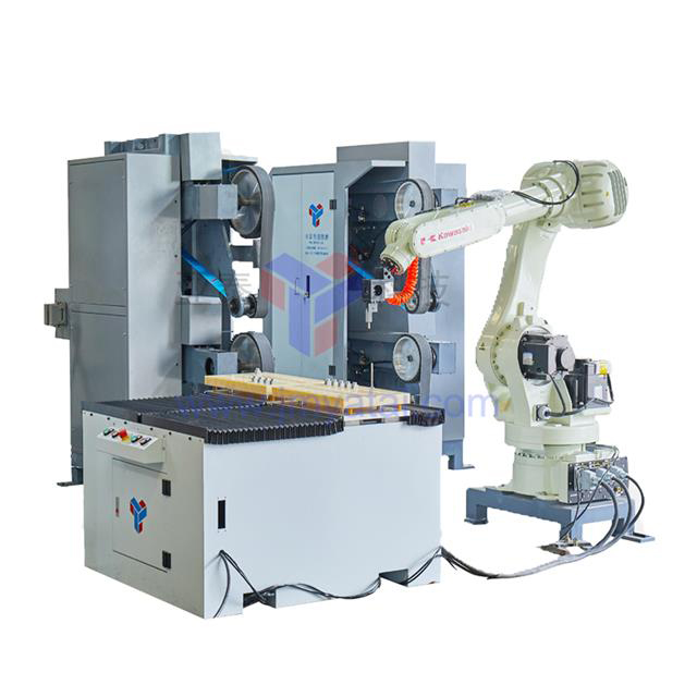
Automated finishing
Improving repeatability for suitable parts and production volumes
Requires appropriate fixturing, tool paths, and process validation
The choice of equipment should follow a sample evaluation that considers the workpiece geometry, defect location, material removal allowance, cycle time, and finished-part criteria.
Conclusion
Die casting defects can increase scrap, rework, and product failure risks, but systematic process control can reduce their occurrence. Effective prevention begins with understanding the defect, confirming its root cause, and selecting a corrective action that addresses the source.
Engineering teams should combine DFM, process monitoring, melt quality control, tooling maintenance, and appropriate inspection. Procurement teams should evaluate suppliers through documented evidence of process control and corrective-action effectiveness.
For surface defects such as flash, burrs, and selected irregularities, secondary finishing may improve part consistency when the defect is suitable for material removal. Structural problems such as serious porosity or cracks require a different response and should not be treated as polishing issues.
Before approving a production supplier, define the acceptance criteria, review the validation plan, and confirm that the process can consistently meet the component's functional and dimensional requirements.
FAQs
1. What are the most common die casting defects?
Common defects include gas porosity, shrinkage porosity, inclusions, cold shuts, misruns, flow marks, flash, cracks, and dimensional mismatch. Their significance depends on the component's function and the applicable acceptance criteria.
2. What causes porosity in die casting?
Gas porosity may result from trapped gas, turbulent filling, inadequate venting, or release-agent conditions. Shrinkage porosity is associated with solidification contraction and local feeding conditions. Inspection and root cause analysis help distinguish between them.
3. How can manufacturers prevent die casting defects?
Prevention includes reviewing part design, optimizing gating and venting, controlling injection and thermal conditions, maintaining melt quality, and inspecting tooling. Process monitoring and production validation help verify whether corrective actions work.
4. Can die casting defects be repaired?
Some surface defects may be removed or improved through trimming, deburring, grinding, or polishing. Structural defects such as serious cracks or unacceptable internal porosity usually require rejection or a formally approved repair process. Acceptance must follow the applicable engineering requirements.
5. Can polishing remove die casting defects?
Polishing can improve suitable surface irregularities and appearance, but it cannot reliably correct internal porosity, structural cracks, or serious material inclusions. Confirm the defect type before choosing a finishing process.