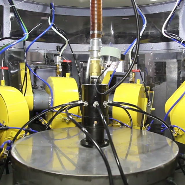
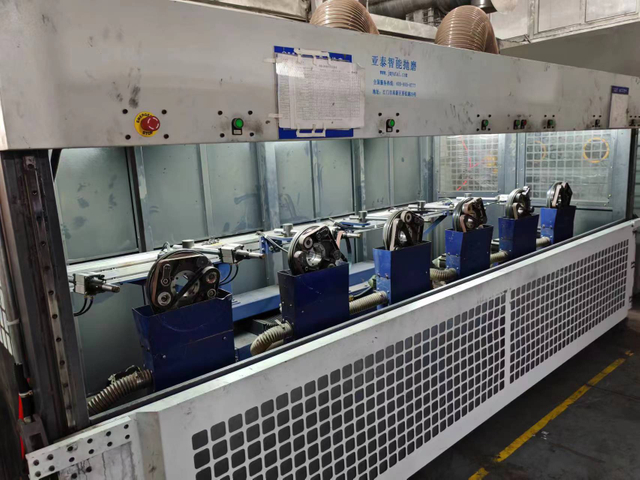
High-volume die casting operations face a persistent bottleneck. Rapid casting cycles push parts out quickly, but slow manual finishing grinds production to a halt. Manual flash removal introduces variable edge quality and high scrap rates. It creates ergonomic safety liabilities and leaves facilities dependent on scarce manual labor. You cannot scale a precise manufacturing operation when the final step relies on hand tools and human endurance. Automated finishing systems solve this core business problem. Implementing a reliable Deburring Machine stabilizes cycle times and ensures immediate assembly readiness. It protects profit margins on complex die-cast components by removing unpredictable human variables from the production floor. Upgrading to automated edge blending and flash removal is a necessary step for modern casting facilities.
Labor Efficiency: An automatic deburring machine typically offsets the workload of two or more manual operators per shift, reallocating labor to higher-value quality assurance tasks.
Technology Alignment: Selecting between robotic (force-controlled EOAT), vibratory, or CNC deburring depends strictly on part geometry, material (Aluminum, Zinc, Magnesium), and required edge tolerances.
Quality Standardization: Automated systems eliminate the human variable, yielding a 100% reduction in missed operations and ensuring absolute consistency in parting line and flash removal.
The Bottleneck in Die Casting: Framing the Automation Requirement
Defining Success Criteria
A successful automated finishing implementation requires strict baseline metrics. The automated cell must match or exceed the cycle time of the primary die-casting cell. It must achieve specific micro-inch finish tolerances without deviation. The system must also maintain the dimensional integrity of the base casting. If the machine alters critical dimensions while removing flash, the implementation fails. You must define these parameters before selecting equipment. We often see facilities install equipment without establishing a baseline for edge break tolerances, leading to immediate quality rejections. Establish a clear standard for acceptable flash removal before programming the first tool path.
Cycle time alignment dictates the entire cell layout. If the casting press cycles every 45 seconds, the finishing station must clear the part in 40 seconds to allow for transfer and loading. When a single spindle cannot meet this demand, you must design a multi-station cell. We use time studies on manual operations to establish the absolute maximum allowable time for the automated sequence. This data drives the selection of spindle horsepower, feed rates, and abrasive media aggressiveness.
The Limitations of Manual Processing
Manual flash removal and edge blending present harsh realities on the shop floor. Over-machining and under-machining are inevitable when operators use hand grinders. Operator fatigue sets in quickly, leading to degraded quality as the shift progresses. Hand tooling simply cannot maintain the precise pressure required to trace complex parting lines consistently. This variability directly inflates scrap rates and rework costs. We track defect rates across multiple shifts and consistently find a spike in missed operations during the final two hours of a manual shift.
Ergonomic hazards compound the inefficiency of manual finishing. Operators holding vibrating pneumatic tools for eight hours develop repetitive strain injuries. The physical force required to push a carbide burr through heavy zinc flash damages wrists and elbows. Facilities face rising workers' compensation claims and high turnover rates in finishing departments. You cannot build a stable production schedule when your finishing department suffers from chronic understaffing due to injury and fatigue.
Comparative Framework: Traditional Hand-Tooling vs. Modern Automated Systems
Comparing manual methods to automated systems reveals stark operational differences. Automated systems drastically reduce defect rates and improve overall safety. We use specific metrics to evaluate the transition from hand tools to automated cells.
Metric
Traditional Manual Tooling
Automated Systems
Missed Operations Rate
High (Prone to human error)
0% (Programmed consistency)
Edge Accuracy
Variable across operators
Highly Repeatable
Surface Finish Consistency
Inconsistent across shifts
Absolute consistency
Operator Injury Risk
High (RSI, lacerations)
Minimal (Operators isolated)
Cycle Time Variance
+/- 15 seconds per part
+/- 0.5 seconds per part
Impact on Downstream Assembly
Inconsistent finishing wreaks havoc on downstream assembly processes. Poorly blended edges prevent gaskets from seating correctly, leading to fluid leaks in automotive applications. Unremoved flash causes severe mating issues during secondary CNC machining stages. When a part with heavy flash enters a CNC fixture, it sits out of alignment. The subsequent machining operations cut out of tolerance, destroying the part. These defects ultimately result in part rejection at final inspection.
A dedicated Deburring Machine prevents these downstream failures by ensuring every component meets exact geometric requirements before leaving the casting cell. We integrate automated finishing directly after the trim press to catch flash issues immediately. This prevents defective parts from accumulating in work-in-progress inventory. Clean, consistent edges allow automated assembly equipment to handle the castings without jamming or misaligning.
Robotic systems utilize 6-axis arms equipped with force-compliant End-of-Arm Tooling (EOAT). This compliance allows the tool to trace complex contours while maintaining constant pressure against the part. The primary use case involves complex, contoured die-cast parts. These parts require precise flash removal along irregular parting lines without altering the base geometry. The robot path follows the general contour, while the pneumatic compliance device absorbs variations in the casting.
Robotic cells offer dual-phase processing capability. A single robotic cell can process heavy raw casting flash and then switch tools to handle post-machining precision micro-burrs. We program tool change routines that swap a heavy carbide burr for a fine abrasive brush within seconds. This flexibility allows one cell to perform the work of multiple manual stations. You must select a robot with sufficient payload capacity to handle the heavy spindle and the reactive forces generated during cutting.
Programming these systems requires specific techniques. We use offline programming software to generate the initial tool paths from the part's CAD model. We then refine the path on the floor, adjusting the approach angles to prevent the spindle housing from colliding with the part. The force control parameters require careful tuning. Too much pressure gouges the aluminum; too little pressure leaves flash behind.
Vibratory and Mass Finishing Machines
Tub or bowl-style vibratory machines utilize abrasive media and mechanical vibration to process parts. Wide-opening VB(B) series machines handle bulk processing efficiently. The primary use case is the bulk finishing of smaller, less fragile die-cast parts. These systems perform simultaneous deburring, cleaning, and polishing. Wide-opening designs provide a massive advantage for automated part loading, unloading, and media separation. They integrate seamlessly into continuous flow production lines.
Media selection dictates the success of a vibratory process. Ceramic media provides aggressive cutting action for heavy zinc flash. Plastic media offers a softer touch for aluminum parts requiring a smooth surface finish. We match the media shape to the part geometry to prevent lodging in blind holes. A cylindrical media might clean a flat surface well but wedge tightly into a tapped hole, requiring manual removal.
Load parts and media into the vibratory bowl.
Introduce water and compound to lubricate the process and suspend metal fines.
Run the vibration cycle for the determined duration.
Engage the separation screen to discharge parts while retaining media.
Route parts through a drying tunnel to prevent oxidation.
CNC and Dedicated Spindle Deburring
Dedicated multi-axis CNC stations provide rigid, high-precision edge chamfering. These machines use fixed spindles and precise tool paths to cut away burrs. The primary use case involves high-tolerance automotive or aerospace components. In these applications, burr removal must meet exact geometric dimensioning and tolerancing (GD&T) standards. CNC systems offer unmatched rigidity for heavy material removal on critical mating surfaces.
We deploy dedicated CNC stations when the edge break tolerance is tighter than +/- 0.005 inches. A compliant robotic tool cannot hold this tolerance reliably. The CNC machine uses hard fixturing to lock the part in place. Solid carbide chamfer mills trace the edges, producing a perfect, uniform bevel. This method requires highly consistent input parts. If the casting shifts or warps, the rigid CNC tool will cut too deep or miss the edge entirely.
Technical Evaluation Dimensions: Matching Machine to Application
Material-Specific Considerations
Different casting materials require specific machining approaches. Aluminum produces gummy burrs that easily clog standard abrasives. You need specific cutter geometries or specialized media to prevent material loading. We use single-flute carbide routers with polished flutes to evacuate aluminum chips quickly. If you use a standard multi-flute end mill, the aluminum will weld to the tool within minutes, destroying the part and the spindle.
Zinc produces heavier, denser flash. Processing zinc requires aggressive but controlled material removal to clean parting lines effectively. We run higher spindle speeds and heavier feed rates when cutting zinc. The tooling must withstand significant impact forces when encountering thick flash at the ejector pin locations.
Magnesium presents critical safety hazards. You must implement explosion-proof extraction and wet-dust collection systems when machining combustible magnesium dust to prevent catastrophic facility fires. We never run magnesium dry. The automated cell must flood the cutting zone with coolant to suppress sparks and immediately wash the chips into a specialized filtration system. Standard dust collectors will ignite if exposed to magnesium fines.
Part Geometry and Edge Tolerance
Evaluate your parts based on internal versus external burrs. Cross-hole intersections and blind tapped holes require specialized tooling to reach hidden burrs. We use flexible hones or specialized cross-hole deburring tools that expand inside the bore. The rigidity of the chosen machine directly impacts its ability to hold tight edge-break tolerances. Flexible robotic arms handle external contours beautifully, while rigid CNC spindles excel at internal cross-hole deburring where tool deflection must remain near zero.
Thin-walled castings require delicate handling. A heavy robotic spindle pushing against a thin aluminum wall will distort the part. We program the robot to support the back side of the wall with a custom fixture while cutting the front side. This prevents deflection and ensures a clean cut. You must analyze the part's structural integrity before applying cutting forces.
Managing Input Part Variation
Die-cast parts exhibit natural fluctuations in flash thickness due to die wear. Automated systems must adapt to these variations without manual recalibration. Force sensor feedback allows robotic systems to adjust feed rates dynamically. If the tool encounters heavy flash, the system slows down to remove it cleanly. This dynamic adaptation ensures consistent edge quality regardless of minor input variations from the casting cell.
We install vision systems to inspect the part before it enters the cutting zone. If the vision system detects a massive piece of flash that exceeds the spindle's capacity, it rejects the part automatically. This prevents catastrophic tool breakage and spindle damage. The automated cell must possess the intelligence to recognize when a part falls outside the acceptable input parameters.
Scalability and Cycle Time Alignment
You must calculate the required throughput of the finishing system accurately. The automated cell cannot become a secondary bottleneck behind the primary die-cast cell. Time studies must verify that the machine can process parts faster than the casting cycle time. If a single robot cannot keep up, you may need to implement dual-spindle setups or multi-robot cells to maintain continuous production flow.
We design cells with modular expansion in mind. We leave floor space for a second robot and size the safety fencing to accommodate future additions. When production volumes increase, we simply drop in another robot and duplicate the program. This scalable approach prevents the need for a complete cell redesign when demand spikes.
Overall Value and Conceptual Trade-Offs
CapEx vs. OpEx in Automated Deburring
Robotic systems require a high initial capital expenditure but offer immense flexibility. Vibratory systems present a lower upfront cost but carry higher ongoing consumable and media expenses. You must evaluate a realistic timeline for return on investment based on labor reduction. Replacing two or more manual operators per shift significantly accelerates the payback period. Factor in the dramatic reduction in scrap and rework when calculating the true financial impact of automation.
Consumable costs dictate the long-term viability of the process. A robotic cell using carbide burrs might consume fifty dollars in tooling per week. A large vibratory bowl might consume five hundred dollars in abrasive media and chemical compounds in the same timeframe. We track these operating expenses meticulously during the proof-of-concept phase to ensure the facility understands the ongoing financial commitment.
Flexibility vs. Specialization
Technical buyers must evaluate the trade-off between flexibility and specialization. A highly flexible robotic cell can be reprogrammed quickly for different castings. This suits high-mix, low-volume facilities perfectly. Conversely, a hard-tooled, dedicated machine built for a single high-volume part run offers faster cycle times but zero flexibility. Choose the architecture that aligns with your facility's production schedule and future contract pipeline.
We see facilities make the mistake of buying a dedicated CNC machine for a part contract that ends in six months. When the contract expires, the machine sits idle because it cannot be easily retooled. A 6-axis robot equipped with a versatile Deburring Machine spindle can transition to a completely different part family with a simple gripper change and a new program.
Implementation Realities and Risk Mitigation
Integration with Existing Die-Cast Cells
Adding automated systems inline requires careful footprint and floor space planning. You must identify available space near the casting press or trimming station. Part presentation logistics are critical for success. You will need vision systems, custom pneumatic fixturing, or conveyor integration to feed the machine accurately. The robot cannot process the part if it cannot locate it precisely in space.
We utilize gravity chutes or indexing conveyors to move parts from the trim press to the robotic cell. The part must arrive in a repeatable orientation. If the part tumbles down a chute randomly, the robot requires a 3D vision system to locate and pick it. This adds significant cost and complexity to the integration. Designing a simple, mechanical orientation device saves thousands of dollars in vision hardware.
Facility and Utility Requirements
Automated equipment demands robust facility infrastructure. You must provide a clean, isolated electrical supply to protect sensitive controllers. Force compliance devices require high-volume, stable pneumatic air pressure to function correctly. Mass finishing systems need dedicated coolant filtration and wastewater management infrastructure. Verify your facility can support these utility requirements before installation begins.
Air pressure fluctuations destroy the effectiveness of force-compliant tooling. If the plant air pressure drops when a large press cycles, the robotic spindle will lose its compliance pressure and gouge the part. We install dedicated air receivers and high-flow regulators directly at the robotic cell to guarantee stable pressure. Wastewater from vibratory bowls contains heavy metals and abrasive sludge. You must route this effluent through a centrifuge or chemical flocculation system before discharging it to the municipal sewer.
Programming Complexity and Tool Wear
Programming robotic paths for complex parting lines involves a learning curve. Offline programming software helps mitigate this, but operators still need specialized training. Tool wear is a harsh reality when cutting abrasive die-cast materials. You must implement automated tool-wear compensation and tool-life tracking algorithms. Automatic tool-change routines are necessary to prevent unexpected downtime and maintain continuous operation throughout the shift.
We program the robot to measure the tool length on a laser presetter after every fifty parts. As the abrasive brush wears down, the robot automatically adjusts its TCP (Tool Center Point) to compensate for the reduced diameter. When the brush reaches its minimum usable diameter, the robot drops it in a discard bin and loads a fresh tool from the magazine. This closed-loop system eliminates the need for manual operator intervention.
Conclusion
The transition to automated finishing is no longer optional for high-volume die casters. Maintaining competitive pricing, strict quality standards, and safe working conditions requires eliminating manual hand-tooling. Automated systems provide the consistency and speed necessary to keep pace with modern casting cells. Your choice between robotic, vibratory, or CNC solutions must be dictated by part complexity, material safety requirements, and production volume. Never force a technology into an application where it does not belong. Match the machine's capabilities directly to your specific geometric and material constraints.
As a premier global innovator in heavy-duty industrial automation and automated edge-blending technologies, Yatai engineers advanced, high-performance deburring machine solutions custom-optimized for the rigorous demands of the modern foundry environment. Our specialized multi-axis robotic workstations and intelligent mass finishing systems seamlessly integrate active compliance tracking, automated tool-wear calibration, and robust explosion-proof extraction setups, empowering global manufacturers to eliminate secondary machining bottlenecks, minimize consumable overhead, and maintain an injury-free shop floor.
To achieve maximum efficiency on your automated transition, follow these actionable steps:
Audit your current manual finishing operations to identify the exact cycle times and defect rates.
Select three high-volume, high-scrap part numbers to serve as test cases for automation.
Ship raw, untrimmed castings to an equipment integrator for a formal proof-of-concept and time study.
Verify that your facility possesses the necessary electrical, pneumatic, and wastewater infrastructure to support the new equipment.
FAQ
Q: What is the average ROI timeline for an automatic deburring machine?
A: The industry average ranges from 12 to 24 months. This timeline factors in direct labor savings, significant reductions in scrapped parts, and ongoing consumable costs. High-volume operations running multiple shifts typically see faster returns.
Q: Can a robotic deburring machine handle variations in die-cast flash?
A: Yes. Robotic systems utilize force-controlled End-of-Arm Tooling (EOAT) and active compliance devices. These allow the cutting tool to ride along the part edge, dynamically adjusting pressure and feed rates to accommodate variations in flash thickness.
Q: What is the best deburring method for aluminum die castings?
A: It depends on part geometry. Vibratory finishing works best for bulk processing of smaller parts. Robotic routing is superior for precision parts requiring complex parting line cleanup. Aluminum requires specialized tooling to prevent material loading.
Q: How do automated deburring systems improve workplace safety?
A: Automated systems eliminate repetitive strain injuries caused by heavy hand grinders. They remove operators from laceration risks and effectively contain hazardous metal dust within enclosed, ventilated machining cells.
Q: Do vibratory deburring machines alter the dimensions of the part?
A: Vibratory machines are generally safe for overall part dimensions. However, using overly aggressive media or excessive cycle times can round critical sharp edges or alter tight-tolerance machined surfaces if the process is not properly calibrated.